|
This web page provides background material and extra details of the work
described in the paper:
Chih W. Khoh and Peter Kovesi
Rotating the Impossible Rectangle
Leonardo, June 2001, Vol. 34, No. 3, Pages 197-198
Animating Impossible Objects
Chih W. Khoh and Peter Kovesi
Department of Computer Science & Software Engineering
The University of Western Australia
Crawley, W.A. 6009
February 1999
Abstract
Three-dimensional models of impossible objects can only be viewed from
one angle - otherwise they no longer look impossible. But is it
possible to create an interactive impossible object, that is, an
impossible object that can be viewed from any angle? This paper
explores the creation of such objects on the computer. To allow an
impossible object to be viewed from any angle its 3D geometry must be
altered to suit the viewpoint. We show that a particular class of
impossible figures can be described in terms of two complementary
halves. The complementary halves are related to each other by an
inversion transformation in the image plane. They are also related
via a surface visibility reversal transformation. Either one of the
complementary halves can be realized as a 3D object with the
appropriate geometry to ensure an impossible figure will be produced.
The 3D model of one of the complementary halves can be animated by
normal means. Once an arbitrary view has been generated, the other
complementary half can then be constructed by inversion to complete
the impossible figure.
Keywords: Impossible Object, Animation, Complementary Half.
Introduction
An impossible figure is commonly defined as being a two-dimensional
image that is interpreted to give the impression of some
three-dimensional object that cannot exist in a three-dimensional world.
The keywords in this definition are ``impression'' and
``interpretation''. For a figure to be judged impossible (or not) it
must first make the impression of some three-dimensional
object. Furthermore, the property ``to be an impossible figure'' is
not the property of the drawing alone, but the property of its spatial
interpretation by a human observer [9].
However, in many cases it is possible to construct a
three-dimensional model of the impossible figure. This model will not
correspond to the normal interpretation of the figure by a human.
Typically the 3D model must be viewed from a particular direction to
create the illusion of impossibility. For example, 3D models of
Escher's Belvédère [3,10] have been built
by Shigeo Fukuda [2] and models of the impossible tri-bar
and crazy crate have been built by Mathieu Hamaekers [2].
Illustrations of other models can be found at the IllusionWorks web
site [5]. Sugihara [13] describes an
interactive system that allows one to generate polyhedra from
impossible figures, and for drawing the unfolded surfaces of them.
Typically all these 3D models contain a number of gaps or twists. Once
revealed, these gaps and twists destroy the illusion of impossibility
and the model loses its ``magic'' (figure 1). At this
point it is important that we make the distinction between the terms
``impossible figure'', ``impossible object'' and ``3D model''. The 3D
model is a physically realizable object, which when projected
appropriately into 2D, results in an impossible figure. This
impossible figure then gives rise to the perception of an impossible
object (different to the 3D model) which can only exist as an
interpretation in one's mind.
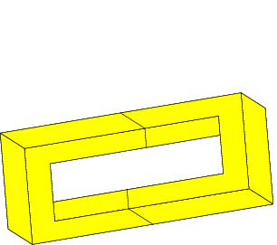
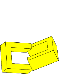
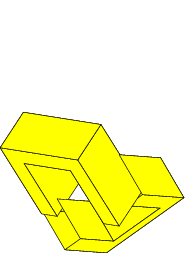
Figure 1:
Three views of a model of an impossible rectangle.
The 3D model consists of two `U' shaped objects. Only the first
view produces an impossible figure
Impossible figures convey the impression of a 3D object and this
strongly implies that one might be able to rotate such an object and
view it from different angles. However, rotation of a 3D model that
corresponds to an impossible figure will immediately reveal the gaps
and twists in the model and the impossible figure will then be
destroyed. A model of an impossible object has to be hand crafted to
suit the desired viewpoint. If the viewpoint changes the model must
be adjusted to suit, but in doing so we must satisfy the following
conditions:
- Components that appear straight from one viewpoint must appear
straight from all viewpoints.
- Components that appear connected from one viewpoint must appear
connected from all viewpoints.
Note that an interactive impossible object does not have to look like an
impossible object from all viewpoints - it is perfectly acceptable
for it to look like a possible object from certain angles, but it would
be expected to satisfy the conditions above.
We can solve this problem by using a computer model of the object
rather than a physical one. The computer provides a tool that allows
us to continuously modify a 3D model so that as the viewpoint changes
its 2D projection continues to satisfy the various properties that
make the figure impossible. The ultimate goal might be to create an
impossible world, like the ones depicted by Escher, that people can
interact with in virtual reality.
Constructing Impossible Figures via Complementary Halves
Penrose and Penrose [11] describe impossible figures as
follows: ``Each individual part is acceptable as a representation of
an object normally situated in three-dimensional space; and yet, owing
to false [connections] of the parts, acceptance of the whole figure on
this basis leads to the illusory effect of an impossible structure.''
A similar view is taken by Huffman [4] who shows that in
general impossible figures will have a locally consistent, but
globally inconsistent, line labelling.
Consider the impossible rectangle shown in figure 2.
This figure is also known as an impossible four cornered torus or
impossible four-bar [1,2]. The key feature
of this impossible figure is that it can be divided into two halves,
which when viewed independently, correspond to a 3D object that is
globally consistent and ``possible''.


Figure 2: An impossible rectangle and its two halves, each of which are
globally consistent.
The important property of these two globally consistent objects is
that they have a projection in the 2D image plane that allows them to
be joined seamlessly to present a locally consistent but globally
inconsistent figure.
We call the projections of the two (globally consistent) halves of the
object, the complementary halves of the impossible
figure [6]. These complementary halves are related by an
inversion transformation. That is, one complementary half can be
obtained from the other via two sequential reflections about
orthogonal axes in the image plane.
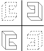
Figure 3: One complementary half can be obtained from the other via
reflections across two orthogonal axes.
Alternatively, rather than working in the image plane, one can think
about constructing the complementary halves in the 3D model space. If
one assumes the projection from 3D to 2D is along the z axis one
can construct the 3D model of the second complementary half by simply
inverting the x and y coordinates of the model of the
first complementary half while leaving the z values unchanged.
This is how the model in figure 1 was constructed. The
3D model of each complementary half of the impossible rectangle is a
`U' shaped object. Each model half has vertices that have negated
x and y coordinates of the other half. Correct alignment
of the 2D projections of the two halves can be assured by chosing the
origin appropriately. In this example the origin is positioned between
the ends of the prongs of the `U' shaped objects.
Yet another approach to the construction of complementary halves is
to use face visibility reversal of the 3D model of the
complementary half. However this approach requires that the
impossible object that we wish to construct has an obvious
corresponding possible object. This process is best illustrated
by example. Figure 4 shows the construction of a
possible rectangle from two halves. If we reverse the visibility
of the faces of the right half (that is, make the hidden faces
visible, and the visible faces hidden) before joining the two halves,
we will produce an impossible rectangle. The process of face
visibility reversal corresponds to the interpretation switch that is
experienced with the Necker Cube (figure 5).


Figure 4: An impossible rectangle can be created by reversing the
visibility of the faces of the right half of a possible rectangle.
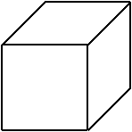
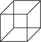
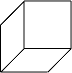
Figure 5: The Necker Cube (centre) and its two interpretations (left and right).
Many impossible figures can be constructed via complementary
halves. Examples include impossible tori (the example shown in
figure 6 is Simanek's Ambiguous
Ring [12]), the impossible stall (upon which Escher's
Belvédère is based), and the crazy crate. Note however, that the
construction of the crazy crate requires an additional step where the
intersection of the lines are resolved.
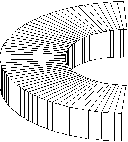
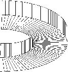 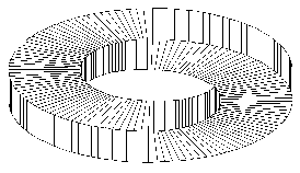
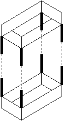
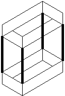


Figure 6: Construction of an impossible torus (top), the impossible
stall (left) and crazy crate (right) via complementary halves.
The use of complementary halves provides a systematic and general way
of constructing convincing impossible figures. Each complementary
half presents a very different `aspect' of an object. That is, the
two complementary halves represent two views of the object from very
different directions. In addition, by definition, the two halves have
the appropriate number of line endings to allow them to join
seamlessly to produce a globally inconsistent figure. Other attempts
to find systematic constructions of impossible figures include the
work of Cowan and Ernst [1,2] who demonstrate how
impossible rectangles can be constructed by combining a fixed set of
corner elements. However, using this approach, the resultant figure
does not always produce a satisfactory impression of an impossible
object. The use of complementary halves to construct impossible
figures is more general and gives a strong guarantee that a convincing
impossible object will be perceived.
The manner in which the inversion transformation that relates the
complementary halves provides two very different aspects of an object
can be illustrated via an aspect
graph [7,8].
Figure 7 shows the aspect graph of a cube. Each node
in the graph represents a generic view, or aspect, of the object. An
aspect of the object is defined as a range of views of the object over
which the topology of the projected image remains unchanged. The
edges in the graph show the possible transitions between aspects. If
we take an aspect of the cube that shows the bottom and two side
surfaces, and apply an inversion transformation to it (or reverse the
visibility of its faces) we will construct a different aspect of the
object, some distance away in the graph, corresponding to a view
showing the top and two side surfaces. Thus, the merging of two
complementary halves can be seen in terms of a simultaneous
presentation of two distant aspects of an object within the one
figure. This creates the impression of impossibility.
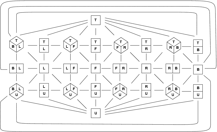
Figure 7: Aspect graph of a cube. The front, left, right, back, top
and under sides of the cube are denoted by the letters F, L, R, B, T
and U respectively.
Rotating the Impossible Rectangle
Animation requires the existence of a 3D model that can be translated
and rotated into different views. Thus, to create an animation of an
impossible figure we must first create a 3D model, which when
projected onto the image plane, results in an impossible figure. This
3D model must then be continuously modified in some way, as the
viewpoint changes, so that the impression of impossibility is
maintained. One approach to this problem might be to employ
Sugihara's method of 3D model construction [13].
However, Sugihara's approach requires that the starting point in the
process is the impossible figure. Once a 3D model has been obtained
it is not clear how one might modify it for a different viewpoint.
Being able to divide an impossible figure into complementary halves
greatly simplifies this task of constructing an appropriate 3D model.
We only have to construct a model that corresponds to one half of the
figure, and typically each complementary half is readily modeled by a
simple 3D object. This gives us the basis of an algorithm for
animating impossible objects composed of complementary halves. The
steps are as follows:
- Construct a 3D model representing one globally consistent half
of the impossible object.
- Orient it to the desired view.
- Construct the other complementary half from the first (noting
that its construction is a function of the desired view of the first
half).
- Display the joined complementary halves in the 2D image plane.
Figure 8 shows the results of rotating an
impossible rectangle. The shaded half-rectangle is the 3D model that we are
rotating and the white half-rectangle is its complementary half
constructed in the image plane.


Figure 8: Rotating the impossible rectangle. The figures on the left
hand side illustrate the process by which the impossible figures on
the right are constructed.
Animation Requires Continuous Modification of the 3D Model
You may have noticed that the impossible rectangle appears thinner on
its side view (the second and third image in the rotation shown in
figure 8). This is a side effect of getting the
lines of each complementary half to join up. In joining the two
halves of the impossible rectangle the top surface of one
complementary half has to be merged with the side surface of the prong
of the other complementary half. That is, the projected widths of the
top and side surfaces must be equal if we are to successfully merge
the complementary halves (figure 9). As the
object rotates the relative widths of the projections of these two
surfaces will vary. To compensate for this we must adjust the
thickness of the 3D model, and/or adjust the height of the sides of
the prongs, so that the projected width of the top surface will match
the side surface. Figure 10 shows this process in the
construction of the crazy crate.

Figure 9: Failure to adjust the thickness of the impossible rectangle
during rotation results in complementary halves that cannot be
joined.
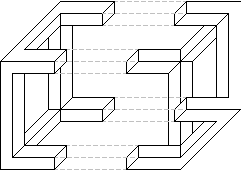
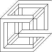
Figure 10: To allow joining of the complementary halves of the crazy
crate in this view the adjoining bars must be made non square in
section.
Thus, we need to refine our animation algorithm as follows:
- Construct a 3D model representing one globally consistent half
of the impossible object.
- Orient it to the desired view.
- Project it into the 2D image plane.
- Calculate the widths of the projections of the surfaces to be
joined.
- Calculate the rescaling required in the projected widths of the
surfaces to be joined so that they match.
- Rescale the widths of the corresponding surfaces in the 3D model
by the required amounts.
- Given the revised dimensions of the first complementary half,
construct the second complementary half.
- Display the joined complementary halves in the 2D image plane.
Projection is a linear operation. Thus, the rescaling required of the
surfaces in the 2D projection to allow the surfaces to be joined will
directly correspond to the rescaling required of the surfaces in the
3D model. Note that there will be some views in which an impossible
object will be degenerate. These will correspond to views in which
the projected width of one of the joining surfaces become zero. No
amount of rescaling of the 3D model will make its projected width
non-zero to permit a match. The only solution is to form a
`degenerate match' by rescaling the 3D width of the surface that has a
non-zero projected width, to zero. Another degeneracy arises when we
attempt to construct an end view of the object. If one thinks of the
complementary halves in terms of the two `U' shaped 3D objects as shown in
figure 1 this situation corresponds to the two objects
rotating into each other so that they merge and become identical.
Examples of these situations can be seen in figure 11.
Overall, the use of complementary halves to describe an impossible
figure greatly simplifies the construction of a corresponding
impossible object. The constant adjustment of the 3D model that is
required with viewpoint changes is reduced to a rescaling of the
dimensions of the object being used to model one of the complementary
halves. In the case of the impossible rectangle this geometry change
manifests itself as a simple thickness and/or height adjustment of the
joining prongs. This constant adjustment in the geometry of the 3D
model contributes an extra aspect to the impossibility of the figure.
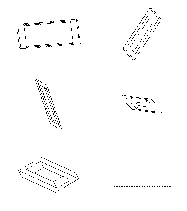
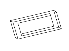
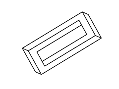
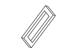
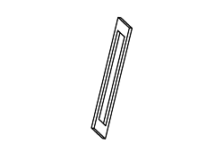
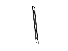
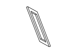
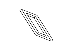
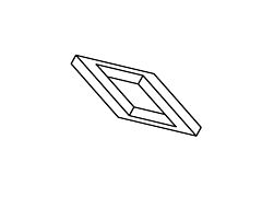
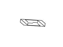
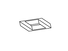
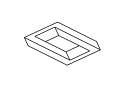
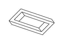
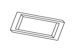
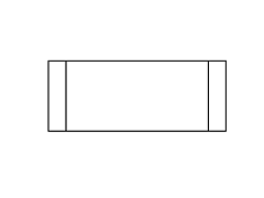 Figure 11: Full rotation sequence of an impossible rectangle. Note the
degeneracies that arise when the object is viewed directly side-on, and when it is viewed near end-on.
Conclusion
Impossible figures can be animated. To do this there are two problems
that have to be solved. Firstly, one has to construct a 3D model that
corresponds to the figure, and secondly, one has to identify how the
3D model must change as the viewpoint changes, so that an impossible
figure continues to be produced.
This paper introduces the concept of a complementary half of an
impossible figure. It is shown how complementary halves can be
constructed either by inversion in the image plane or by face
visibility reversal. The use of complementary halves offers a
systematic way of constructing a particular class of impossible
figures. It facilitates the animation of impossible figures by
greatly simplifying the construction of impossible objects from their
corresponding impossible figures. Only half of the figure has to be
considered and each complementary half is readily modeled by a simple
3D object. The constant adjustment of the 3D model that is required
to maintain the impossible figure as the viewpoint changes, is reduced
to a simple rescaling of the dimensions of the object being used to
model one of the complementary halves. This constant adjustment in
the geometry of the 3D model contributes an extra air of impossibility
to the figure.
Acknowledgment
The authors would like to thank Donald Simanek for permission to use
an illustration of his Ambiguous Ring.
References
- [1]
-
Thaddeus M. Cowan.
The theory of braids and the analysis of impossible figures.
Journal of Mathematical Psychology, 11:190-212, 1974.
- [2]
-
Bruno Ernst.
The Eye Beguiled: Optical Illusions.
Benedikt Taschen Verlag GmbH, 1992.
- [3]
-
M. C. Escher.
The Graphic Work of M.C. Escher.
Pan/Ballentine, London, 1972.
Translated by John E. Brigham.
- [4]
-
D. A. Huffman.
Impossible objects as nonsense sentences.
In Bernard Meltzer and Donald Michie, editors, Machine
Intelligence, volume 6, pages 295-323. Edinburgh University Press, 22
George Square, Edinburgh, Great Britain, 1971.
- [5]
-
IllusionWorks, L.L.C.
IllusionWorks Home Page.
World Wide Web Site. http://www.illusionworks.com.
- [6]
-
Chih W. Khoh.
That's Impossible!, 1998.
Honours Thesis. Department of Computer Science, The University of
Western Australia.
- [7]
-
J. J. Koenderink and A. J. van Doorn.
The internal representation of solid shape with respect to vision.
BioCyber, 32:211-216, 1979.
- [8]
-
J. J. Koenderink and A. J. van Doorn.
Photometric invariants related to solid shape.
Optica Acta, 27(7):981-996, 1980.
- [9]
-
Zenon Kulpa.
Are impossible figures possible?
Signal Processing, 5(3):201-220, May 1983.
- [10]
-
Paul Schofield.
World of Escher.
World Wide Web Site. http://www.worldofescher.com.
- [11]
-
L. S. Penrose and R. Penrose.
Impossible objects: a special type of visual illusion.
British Journal of Psychology, 49(1):31-33, 1958.
- [12]
-
Donald E. Simanek.
Adding Depth to Illusions.
WWW document. http://www.lhup.edu/~dsimanek/3d/illus2.htm,
December 1996.
- [13]
-
Kokichi Sugihara.
Three-dimensional realization of anomalous pictures - an
application of picture interpretation theory to toy design.
Pattern Recognition, 30(7):1061-1067, July 1997.
File translated from TEX by TTH, version 2.00.
On 5 Feb 1999, 15:04.
|