Fibreglass Strength
This is a fairly long web page describing my attempts to understand the strength of fibreglass and my attempts to work out how you can design basic structures in fibreglass that will meet a specified strength. I found remarkably little concrete guidance on the web for doing this. I hope what I have presented below is of some use, and I hope it is reasonably correct! If you use this information for your own projects do so with care and at your own risk.
I was wanting to design a beam to support a load. It was going to consist of a wooden core with a laminate of fibreglass on the upper and lower surfaces forming, in effect, an I-Beam. Given a load on the centre of the beam, and the beam's thickness, one can readily calculate the tension on the lower surface and the compression on the upper surface.
What I wanted to know was how much glass would I need on the upper and lower surfaces so that it could withstand the tension and compression loads? Try as I might I was unable to find any clear guidelines on the web.
What I wanted to know was, using the basic techniques that I could employ in my shed, and using glass cloth and resin that I could buy from my local suppliers, how strong would a layup of a particular weight of glass be?
I could find data for the tensile strength of E-glass (the standard glass one tends to buy). This would typically be in the range from 1700 MPa to 3500 MPa. (Ranging by a factor of two!) To be conservative let's assume it is the lower value of 1700 MPa. What this means is that if I had a large bundle of glass fibres such that the sum of their cross section areas was 1 square metre it could take a load of 1,700,000,000 Newtons to break it under tension. To convert this to an equivalent load in terms of kilograms one divides by gravitational acceleration of 9.8ms^2 which, for simplicity, we will approximate as 10. Thus, according to these numbers this bundle, with a collective cross section of 1 square metre, can take a load in tension of 170,000,000 kg or 170,000 tonnes.
To get these numbers to a scale that is easier for us to relate to we can consider a bundle of fibres with a total cross section of one square millimetre. One square millimetre is 1 millionth of a square metre. If the numbers above are right this would indicate that this bundle could support 170kg of load in tension.
Is this realistic? How can I relate this to the glass in a piece of fibreglass cloth?
6oz cloth is a typical weight for sheathing boats. I decided to do some calculations and experiments with this. 6oz per square yard corresponds to 194 g/m^2. The cloth is woven with strands in two drections, thus if we apply tension to the fabric only half of strands are loaded. That is, we will have 194/2 = 97g of cloth spread over a metre to resist the load. To work out its strength we need to know the cross section area of the 97 grams of fibres. Let's assume the glass is a solid sheet. Noting that the density of glass is 2.54 g/cm^3 we can compute the volume of 97 g of glass as 97/2.54 = 38.2 cm^3. This volume of 38.2 cm^3 is spread over 1 m^2 (10,000 cm^2) so we can compute the thickness of our equivalent sheet of solid glass as 38.2/10,000 = 0.00382 cm, or 0.0382mm.
If we have a strip of this glass 26mm wide it will have a cross section area of 26 x 0.0382 = 0.993 mm^2, approximately one square millimetre. The obvious thing to do now is lay up some glass, cut it into strips, and see what load is needed to break them. Can it support 170kg?
I created a layup approximately 300mm x 300mm of 2 layers of 6oz cloth from which I could cut strips that I could test to destruction. At the top and bottom edges of the test panel I added extra layers of cloth to create a solid region through which anchoring holes could be drilled. A total of 10 layers of cloth were added with the number of layers tapering down to the central 2 layer section to avoid creating a point of stress concentration.
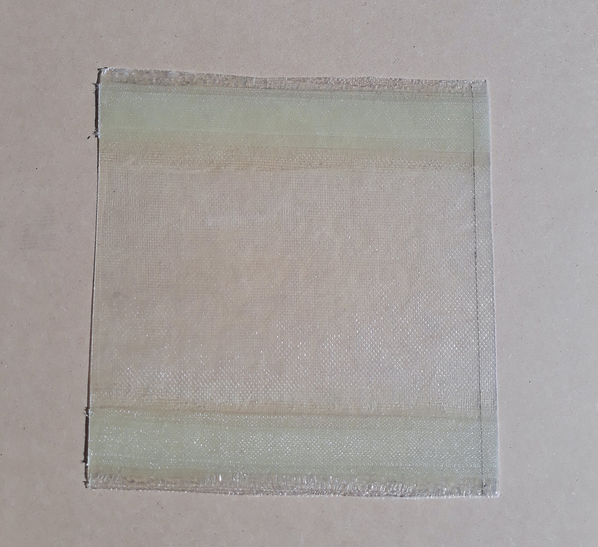
From this panel I cut strips approximately 10 to 12 mm wide for testing. I aligned the strips as close as I could the the direction of the weave so that all the strands were stressed directly in tension. I cut them, cleaned the edges, and then measured the final width carefully. Noting that the laminate was formed from two layers of cloth the actual width of 6oz cloth was twice the cut strip width, approximately 20 to 24mm wide. Anchoring holes were drilled at the ends of the test pieces.
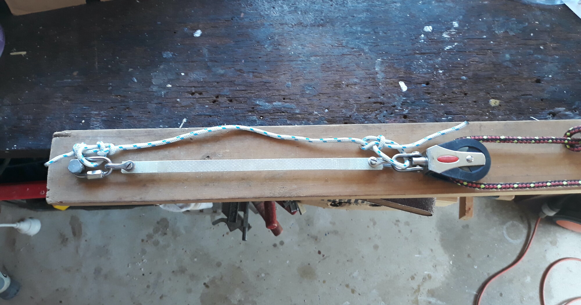
Here's the test rig. A timber beam with the test sample anchored at one end and an 8:1 pulley system at the other. To minimise friction I used a cascading pulley arrangement so that only 3 pulleys were involved. A spring balance was used to measure the force applied to the pulley system until the glass sample failed. The spring balance had an indicator that would be pushed down its scale and record the maximum tension that was achieved. The spring balance had a maximum capacity of 22kg so with the 8:1 system I could exert a force of 176kg.
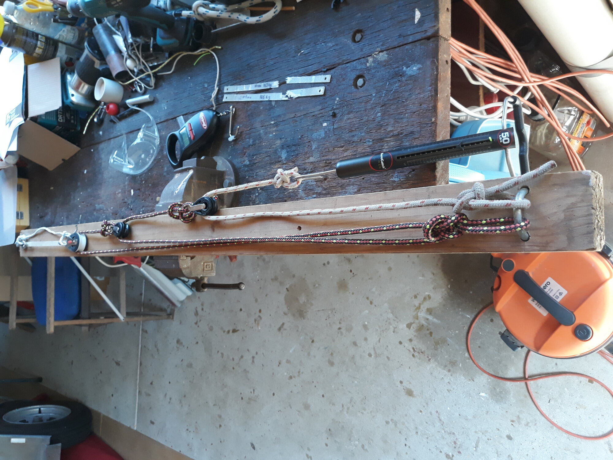
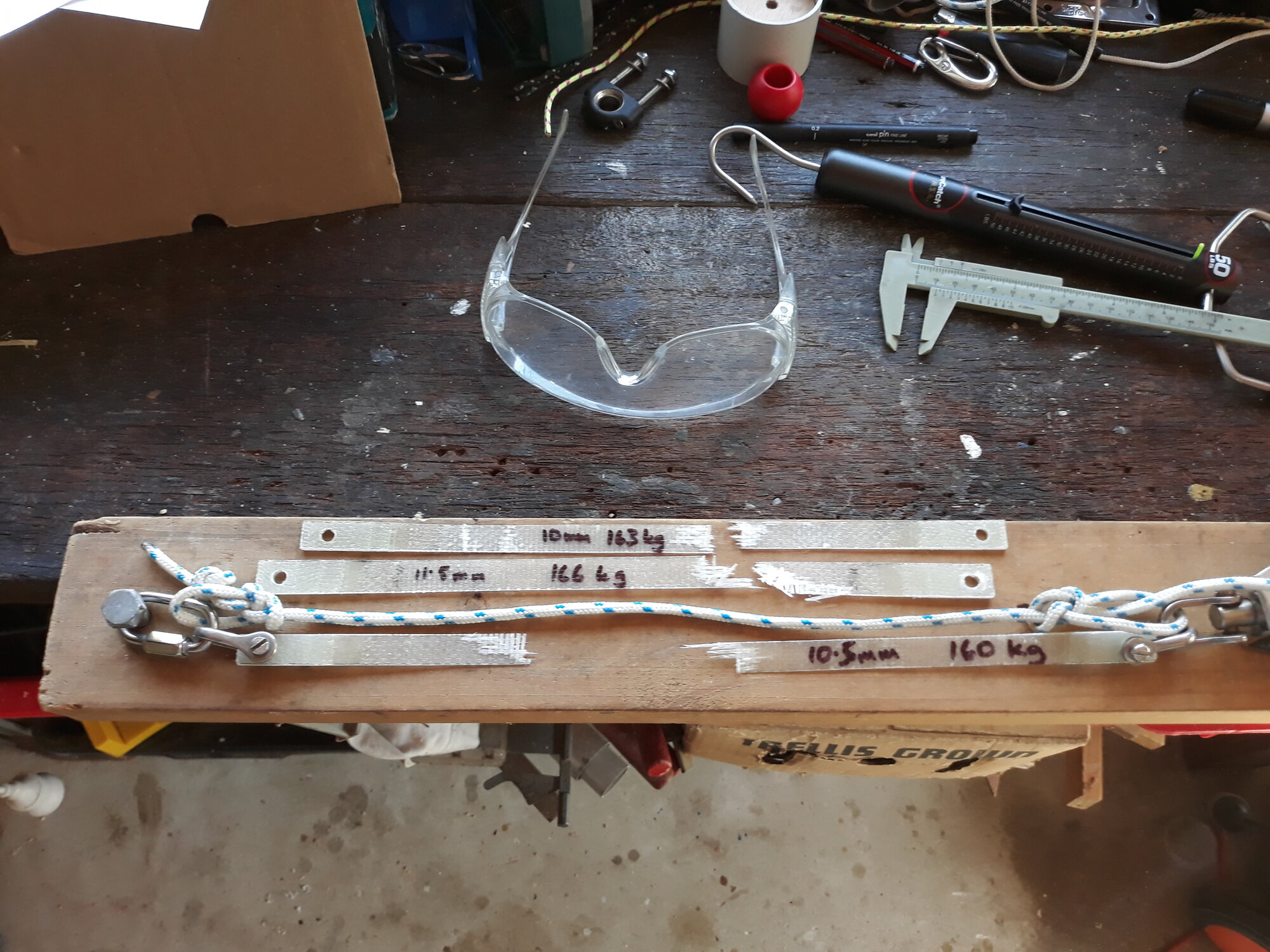
It is a bit scary applying such a large force until something breaks. Safety glasses are definitely required. A short length of rope to stop the pulley system recoiling violently after the sample breaks was added after the first test! Gloves are also a good idea and were also added after the first test.
Three tests were conducted with pleasingly consistent results. I did not feel the need to conduct any more. It was quite satisfying to find that theory and experiment matched up quite well.
From the failures of the test pieces I could then calculate an estimate of the tensile strength of the glass.
	10mm failed at 163 kg
	Cross section of glass = 20mm x 0.0382mm = 0.764mm^2
	Tensile strength = 163 * 10 / (0.764 * 1e-6)  = 2.13 GPa


	11.5mm failed at 166kg
	Cross section of glass = 23mm x 0.0382mm = 0.879mm^2
	Tensile strength = 166 * 10 / (0.879 * 1e-6) = 1.89 GPa


	10.5mm failed at 160kg
	Cross section of glass = 21mm x 0.0382mm = 0.802mm^2
	Tensile strength = 160 * 10 / (0.802 * 1e-6) = 1.99 GPa
In the calculations above the kilogram force is multiplied by 10 to get a
force in Newtons. The area in square milimetres is multiplied by
1/1,000,000 (1e-6) to convert to square metres. The force divided by area gives
the tensile strength (a pressure).
The experimental values of tensile strength between 1.9 and 2.1 GPa fits in at the lower range of tensile strengths that are generally quoted. I think this is reasonable as the fibres are not straight, but crimped as a result of being woven. I would expect non-woven fabrics, unidirectional and multiaxial fabrics, where the glass tows are sewn togeter and kept flat, to be stronger and closer to the quoted maximum strengths. In the case of woven fabric one would certainly expect the crimping of the fibres to reduce compressive strength.
Note that I have ignored the contribution of the epoxy resin to the strength of the laminate. The tensile strength of epoxy is about 50 MPa which is very, very much less than glass. Its primary role is to bind the fibres together and allow loads on fibres to be transmitted and shared with neighbouring fibres. In compression it serves to support the fibres, keeping them in column so that the laminate does not fail by buckling.
It is worth noting that epoxy is superior to polyester for three reasons: It is stronger, it will take a higher degree of strain (stretch) before failing, and it bonds more strongly to the fibres. Once the strain (stretch) on a laminate is such that the resin starts to crack away from the fibres the load on any fibres can no longer be transmitted and shared with neighbouring fibres and the laminate fails rapidly. Epoxy having a better bond to the fibres, and being more flexible, ensures the integrity of the laminate is preserved under higher loads.
Some worked examples of strength
Disclaimer
Note in all the calculations below I
have not done any rounding of the resulting numbers. I have
simply used them as they have come out. Please do not presume
that because I have provided a force down to a level of 10 N
(say, 7640 N) that the accuracy of the results are to that
precision. All the input strengths of the materials are
somewhat indicative and thus the computed strengths can only be
indicative. All these results should be used conservatively
with a suitable safety margins. If you are wanting to use these
results in a project of your own you should satisfy for yourself
that the calculations presented here are correct. If you find
any mistakes please let me know!
6oz cloth 100mm wide
	6oz => 194g/m^2
	97g/m^2 oriented in one direction
	Volume of glass over 1m^2 = 97g / (2.54x10^6)g/m^3 = 0.0000382m^3

	Cross section thickness over 1m^2 = 0.0000382m   ( = 0.0382mm )
	Cross section area over 100mm width of cloth = 0.1m x 0.0000382m = (3.82 x 10^-6)m^2

	Assuming a strength of 2GPa (from my experiments above) the 100mm width of cloth will fail at a load of
	(2 x 10^9)Pa x (3.82 x 10^-6)m^2 = 7640N   approximately 764kg
10oz cloth 100mm wide
	10oz => 340g/m^2
	170g/m^2 oriented in one direction
	Volume of glass over 1m^2 = 170g / (2.54x10^6)g/m^3 = 0.0000669m^3

	Cross section thickness over 1m^2 = 0.0000669m   ( = 0.0669mm )
	Cross section area over 100mm width of cloth = 0.1m x 0.0000669m = (6.69 x 10^-6)m^2

	Assuming a strength of 2GPa the 100mm width of cloth will fail at a load of
	(2 x 10^9)Pa x (6.69 x 10^-6)m^2 = 13380N   approximately 1338kg
450gsm biaxial cloth 100mm wide
	225g/m^2 oriented in one direction
	Volume of glass over 1m^2 = 225g / (2.54x10^6)g/m^3 = 0.0000886m^3

	Cross section thickness over 1m^2 = 0.0000886m   ( = 0.0886mm )
	Cross section area over 100mm width of cloth = 0.1m x 0.0000886m = (8.86 x 10^-6)m^2

	Assume a strength of 3GPa because the fibres are straight rather than woven.
        This is just a guess on my part that I hope is conservative given the typically
	quoted glass strength of 3.4GPa.

	With this assumption the 100mm width of cloth will fail at a load of
	(3 x 10^9)Pa x (8.86 x 10^-6)m^2 = 26580N   approximately 2658kg
600gsm quadaxial cloth 100mm wide
	The effective fraction of fibres oriented in one direction are (1 + 2 x cosine(45 degrees)) / 4 = 0.6
	0.6 of 600g/m^2 = 360g/m^2 effectively oriented in one direction

	Volume of glass over 1m^2 = 360g / (2.54x10^6)g/m^3 = 0.0001417m^3

	Cross section thickness over 1m^2 = 0.0001417m   ( = 0.1417mm )
	Cross section area over 100mm width of cloth = 0.1m x 0.0001417m = (1.417 x 10^-5)m^2

	Again, assuming a strength of 3GPa the 100mm width of cloth will fail at a load of
	(3 x 10^9)Pa x (1.417 x 10^-5)m^2 = 42510N   approximately 4251kg
170g unidirectional carbon tape 65mm wide
	Volume of carbon over 1m^2 = 170g / (1.8x10^6)g/m^3 = 0.0000944m^3
	(Carbon density 1800kg/m^3)

	Cross section thickness over 1m^2 = 0.0000944m   ( = 0.0944mm )
	Cross section area over 65mm width of tape = 0.065m x 0.0000944m = (6.136 x 10^-6)m^2

	Assuming a strength of 3.5GPa  (Hopefully a reasonably conservative estimate)
	the 65mm width of tape will fail at a load of
	(3.5 x 10^9)Pa x (6.136 x 10^-6)m^2 = 214760N   approximately 2147kg
Glass and carbon fibre is incredibly strong!
Examples of beam designs
A note on compressive strength of glass and carbon
While there is plenty of data describing the tensile strength of
glass and carbon I have not found much data on their compressive
strengths. The following analyses assume that glass and carbon
have compressive strength that is at least equivant to its
tensile strength. However, what little information I have found
would indicate that the compressive strength is significantly
less than the tensile strength, perhaps by up to a factor of 2
in some cases. Accordingly a significant safety factor should
be applied when using the results below. An additional
assumption is that the bond of the glass or carbon to the core
material is such that compression loads do not fail as a result
of buckling of the glass or carbon.
Ring frame on Sweet Pea
To keep the cabin area on my Sweet Pea as open as possible I wanted to have a ring frame that supported the hull and deck mid-way through the cabin area rather than a bulkhead. The ring frame is to be constructed from a lightweight western red cedar core 45mm thick glued on the inside of the 9mm ply hull with unidirectional carbon on the inside and on the outside of the ply hull. Thus the total core thickness between the carbon skins is 54mm. The question we want to answer is how much carbon is needed to obtain the strength we need.
The distance across the deck at the ring frame is about 2m. Assume we want to be able to take a load of 300kg at the mid-point of the deck above the ring frame. (Roughly three heavy people all standing at the middle of the deck).
A very simple model of the situation is to assume this corresponds to a straight beam 2m long with simple supports at each end and a 3000N (300kg) load in the middle. This is an excessively crude and conservative model, really what we have in the deck is a shallow arch with the ends of the arch fully supported, that is, cantilevered. However, we will work through this model as a basic benchmark.
                    3000 N
                     |
                     v
         =========================
         ^                       ^
 1500 N  |                       |  1500 N
The 3000N load in the middle is counteracted by two 1500N support forces at each end. The beam is 2m long so at the middle the bending moment (bending lever force) is 1500N x 1m = 1500Nm. This has to be counteracted by carbon skin on each side of the ring frame core.
      ---------------------  <<<--  F
      :::::::::::::::::::::
      :::::::: core :::::::
      :::::::::::::::::::::
      ---------------------  -->>>  F
To generate a counteracting moment of 1500Nm within the ring frame structure across the core thickness of 54mm requires the carbon skin to take a load of
F = 1500Nm / 0.054m = 27777N (roughly 2777kg)
This is a load of nearly 3 tonnes! However, given the strength calculated for the 65mm unidirectional carbon tape we can cover this comfortably using two layers of tape.
A more realistic model of our loaded deck is to assume the ends of the beam are fixed and not free to rotate. (After all the edges of the deck are fixed rigidly to the hull).
                       3000 N
                         |
           /|            v            |/
           /|=========================|/
       ^   /|                         |/  ^
       |                                  |

     1500 N                             1500 N
In this situation the fixed ends of the beam are counteracting some of the bending and thus reducing the bending moment in the middle of the beam.
The equation for the bending moment at the mid point (and at the ends) is
      M =   F x L
           -------
              8

      Where: M is the bending moment
             F is the force on the beam
             L is the length of the beam
You will find this formula as example 16 on this pdf of
Beam
Formulas
For our beam with a length of 2m at the middle
we have
      M =  3000N x 2m
           ---------
               8

        = 750Nm
This is half the bending moment we had for the beam with free ends. Accordingly the load that has to be resisted by the carbon skins is halved to 13888N (approximately 1388kg). One layer of carbon tape should be more than sufficient. But I will put two layers on anyway! This in conjunction with the fact that the deck is more of a shallow arch rather than a straight beam should give me a very large safety margin.
Centreboard layup
The centreplate on the Sweet Pea is approximately 380mm wide at the top tapering to 345mm at the tip. It is 1450mm long with 1050mm extending below the bottom of the hull. It will incorporate about 50kg of lead in the lower section of the board.
I want the plate to withstand a sideways load of 350kg at the tip. (A capsized boat with three people on the end of the plate plus the 50kg of lead.)
The plate thickness will be 38mm. This will be made up of a 34mm timber core with approximately 2mm of glass on each side. Thus the centrelines of the skins of glass will be approximately 36mm apart.
I am planning to use 600gsm quadaxial cloth on the board. The question is how many layers do I need to achieve the strength I want.
The 350kg load at the tip will result in a bending moment of
      M = 3500N x 1.050m
        = 3675Nm
If the skins of glass are about 36mm apart this bending moment results in a force on the skins of
      F = 3675Nm / 0.036m
        = 102083 N
        = 10208 kg   (10 tonnes!)
Given the foil section I estimate only about a 150mm width of glass over the thickest part of the foil will be taking the load. Given the strength calculated above for a 100mm width of 600g quadaxial cloth of 42510 N we can estimate the strength over an 150mm width to be 63765 N.
To achieve a strength of 102083 N we need
102083 N / 63765 N = 1.6 layers
So two layers of the 600g cloth should be sufficient. I will use 3! Indeed, maybe 4 on the top section.
To verify this experimentally I will be making a small test section of 600g quadaxial on each side of a cedar core and will test it using a cantilevered load. Results to come...
Comment on using carbon:
The distinction between strength and stiffness
Carbon is typically treated as being very much stronger than glass. However, one needs to make the distinction between strength and stiffness. Standard HS grade carbon is about 3 times stiffer than glass but perhaps only around 30% stronger.
The Tensile Modulus, or Youngs Modulus, measures stiffness of a material. It is defined as
                    Stress applied in Pa
	            /
                   S
	    E  =  ---
	           e
                    \
		   strain - the relative deformation/stretch
The stress - strain curve for a ductile material, such as steel, will typically look something like this (Wikipedia)
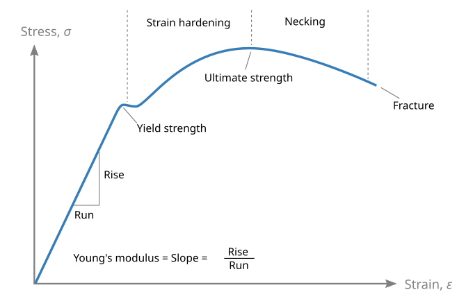
A carbon or glass composite will have a similar behaviour for the first, linear, section of the curve. However, once the yield point is reached the composite will fail, it is not ductile. The slope of the initial linear part of the curve defines the tensile modulus. The steeper the curve the stiffer the material.
The tensile modulus of carbon is about 230GPa (HS standard modulus carbon) (Epsilon website) whereas glass tensile modulus is about 72GPa. Thus carbon is about 3 times as stiff as glass. Indeed, carbon is slightly stiffer than steel. Carbon is also light, having a specific density of 1.8, so in terms of stiffness to weight and strength to weight carbon is an extraordinary material.
The quoted carbon strength seems to vary from about 3000GPa to 5000GPa. For HS grade carbon the strain to failure is about 1.5% to 2%. That is, a relative stretch of 0.015 to 0.02. If we assume a strain to failure of about 0.015 at the bottom of this range we can estimate the load to failure as
      load to failure  =  tensile modulus  x  strain
                       =   230 x 10^9      x  0.015
                       =   3.45 GPa        (similar to glass)
If you are attempting to reinforce some glass with an equal amount of carbon you will find that at the point of failure at a strain of 0.015 the glass will have only taken up a load of
      glass load  = 72 x 10^9   x   0.015
                  = 1.1 GPa
Thus at the point of failure the glass will not have contributed very much in resisting the load.
In general carbon should not be thought of reinforcing something. It is so stiff it ends up pretty well taking the full load and one should design the carbon laminate to do so.
If you are not too concerned about the stiffness of your structure, and only concerned about strength, then you should probably just use glass. It will be much cheaper but, of course, a bit heavier.
Estimating the thickness of a laminate
The formula below is from EpoxyWorks
                          fabric weight     fibre weight fraction in layup
                               /             /
      laminate_thickness  =  Wf       ( Wf/Xf  x (1 - Xf) )
                            ---    +  --------------------
                             pf                pr
                               \                 \
			     fibre density       resin densty
Typical fibre densities are 2.54 g/cm^3 for glass and 1.8g/cm^3 for carbon.
Typical epoxy resin density is 1.12 - 1.18g/cm^3
Typical fibre weight fraction for a hand layup is 0.45 to 0.55 this can increase up to about 0.7 when vacuum bagging.
The first term is the thickness due to the glass content. This is given by the weight of glass divided by the density of glass. The second term is the thickness due to the resin content and I do not really understand it. The expression ( Wf/Xf x (1 - Xf) ) should represent the weight of resin. My intuition is that it should be ( Wf x (1 - Xf) ) That is, the weight of glass times the resin fraction, which is given by (1 - Xf)
Example: 3 layers of 600g quadaxial glass fabric as per my centreboard layup. Assume the formula is right. Assume 0.5 glass fibre fraction in layup and a resin density of 1.14 g/cm^3.
When applying this formula you need to be careful to use consistent units throughout. Here I have converted all units to metres and kilograms.
      thickness  =     3 x 0.6kg            ( 3 x 0.6 / 0.5  x (1 - 0.5) )
                    -----------------    +   -------------------------------
                    2.54 x 10^3 kg/m^3               1.14 x 10^3 kg/m^3

                 =   0.000709 m          +           0.001579 m
                 =   0.002288 m
                 =   2.28 mm
From the test sample I laid up this is about right though, perhaps, slightly thicker than what I achieved. If I apply the formula using the resin weight as ( Wf x (1 - Xf) ) I calculate a thickness of 1.5mm which is a bit thinner than what I achieved.
Glass and Carbon properties quoted by various sources
Note that carbon can come in various grades
– High Strength / Standard Modulus (HS). This is the most common grade
– Intermediate Modulus (IM)
– High Modulus (HM)
– Ultra High Modulus (UHM)
- E Glass Properties from Wikipedia
- Fiberglass
and Glass Technology: Energy-Friendly Compositions and
Applications edited by Frederick T. Wallenberger, Paul A. Bingham.
Available on Google Books
Tensile Strength MPa Tensile Modulus GPa Compression Strength Mpa Density g/cm^3 E-glass 3445 72.3 1080 2.58 Carbon 4900 230 1570 1.8 - Azo Materials E-Glass properties
Azo Materials Article of E-GlassTensile Strength MPa Tensile Modulus GPa Compression Strength Mpa Density g/cm^3 E-glass 1950-2050 72-85 4000-5000 2.58 Carbon 2900 525 2 - MatWeb E glass data
MatWeb Carbon dataTensile Strength MPa Tensile Modulus GPa Compression Strength Mpa Density g/cm^3 E-glass 3450-3790 72.4 2.58 Carbon 4137 242 1.81 - Colan
Tensile Strength MPa Tensile Modulus GPa Compression Strength Mpa Density g/cm^3 E-glass 3400 72 2.54 Carbon HS 3500 235 1.76 Carbon HM 2480 338 1.8 - JPSCM
Data Book
Tensile Strength MPa Tensile Modulus GPa Compression Strength Mpa Density g/cm^3 E-glass 3400-3500 65-75 2.54 - Design Data, Fibreglass Composites Fibreglass Limited, 1977
-
Epsilon
Tensile Strength MPa Tensile Modulus GPa Compression Strength Mpa Density g/cm^3 Carbon HS 4000-5400 220-280 Carbon HM 3500-4700 330-550 - Marine design manual for fiberglass reinforced plastics by Gibbs & Cox 1960 Free to download from the Internet Archive.
- Epoxyworks Calculating the thickness of a laminate.